 |
 News releases News releases |
 |
 |
 |
  PDF Download(PDF Type, 118Kbyte) PDF Download(PDF Type, 118Kbyte) |
 |
 February 10, 2005 February 10, 2005 |
 |
| Development of a highly accurate calibration system for PLL circuit miniaturization |
 |
| - Achieved industry's first integration of a calibration system in PLL and a +/-2% calibration accuracy - |
|
 |
 |
 |
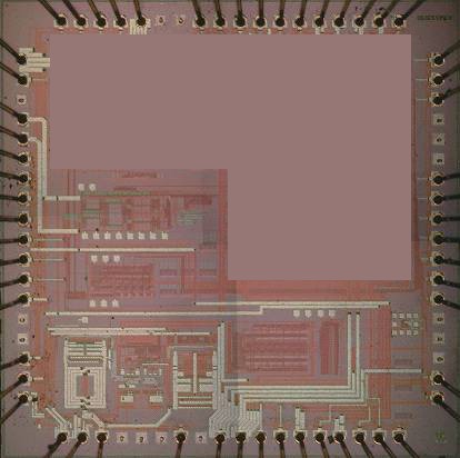
Tokyo, 9th February 2005 --- Hitachi, Ltd. (NYSE:HIT / TSE: 6501) and Renesas Technology Corp. announced today that they have co-developed a highly accurate digital calibration system which can be integrated into RF ICs used in mobile communication devices, such as cellular phones. The integration of a highly accurate loop filter(*1) used for calibration, conventionally as an external component of a PLL (phase-locked loop) circuit(*2) in RF ICs , was achieved without performance deterioration for the first time in industry, and will contribute to the miniaturization and higher performance of RF ICs.
Mobile communication devices have boosted the demand for RF ICs with built-in external components to achieve a more compact size. Hitachi and Renesas Technology have already co-developed several techonologies for higher integration of external components such as low-noise amplifiers, channel filters and oscillators for GSM (Global System for Mobile Communications) handsets. To achieve even further miniaturization, the integration of the loop filter into the PLL circuit was also considered desirable however it has conventionally been located externally for several reasons: (a) the component count, such as resistance and capacitance values, are large; b) if the filter is integrated into the LSI, a drop in analog accuracy occurs due to deviations of the component values resulting in a degradation of calibration accuracy; c) increase in the size of the circuitry, and increase in compensation time.
Thus techniques which would enable the integration of the loop filter within the PLL circuit without degrading calibration accuracy were required.
In response to this challenge, Hitachi and Renesas Technology co-developed a completely new calibration system which integrates the loop filter into the PLL circuit while maintaining highly accurate calibration. Details of the techniques are as below:
| (1) |
Detection of the oscillator's analog characteristics, and compensation, by switching/changing the number of dividing frequencies of the frequency divider: |
 |
The number of dividing frequencies of the frequency divider, a part of the PLL circuit, is changed, and the dividing frequency provided to the oscillator for comparison is increased in steps. The response of the oscillator to the incremental changes (step response) is registered by a counter, which counts the number of oscillator vibrations and periodically calculates the step response by integration to detect variations in the analog characteristics, which is then used for calibration. |
| (2) |
Digital calibration circuit: |
 |
In this calibration circuit the counter needed for detecting the abovementioned step response and the integrator, can be completely fabricated with a digital circuit, thus enabling it to be integrated into the PLL circuit.
The analog characteristics of the PLL circuit depends on factors such as the error feedback level, oscillator control sensitivity, loop filter characteristics, and conventionally each of these characteristics were individually re-calibrated.
|
The new calibration circuit developed corrects all of these performance variations at once, with a +/-2% calibration accuracy which is superior to past accuracy.
This development is expected to become a fundamental technique for achieving compact and high performance RF ICs.
These results were presented at the IEEE International Solid-State Circuits Conference (ISSCC 2005), held in San Francisco, California, U.S.A., from 6th - 10th February 2005.
| Technical Terms: |
| (*1) |
Phase Locked Loop Circuit (PLL):
The PLL circuit compares the frequency and phase of the input signal with the signal from the oscillator located within the circuit, and feedsback the error margin to the oscillator to generate an output signal, thus requiring highly accurate calibration. |
| (*2) |
Loop filter circuit:
The circuit which decides the frequency characteristics of the phase-locked loop circuit which in turn controls the oscillator. |
|
|
 |
| Information contained in this news release is current as of the date of the press announcement, but may be subject to change without prior notice. |
|
 |
 |
PDF files are in Adobe's Portable Document Format. To view them you need Adobe(R) Reader(R) by Adobe Systems Incorporated. |
|
 |
|
 |
|
